Chuck the Duck, world-famous publisher, occasionally pokes good-natured fun at me for “making everything from scratch”. Well this time he can’t say a thing. You see, Chuck used to be a patternmaker. On his Caprice he made the patterns for the aluminum portlights and sent them to a foundry to cast. Casting metal parts has got to be the ultimate in making from scratch.
Well, Chuck, you’ve had what… like ten years to tell us about foundry work? I tell you there’s only so long we can wait. Inquiring minds want to know!
But I guess Chuck can probably make fun of me again, too, since I’m also melting the metal myself. I’m not going to try to give you every little detail of how to cast aluminum. Just show you what can be done with some cheap materials and a (large) chunk of spare time.
Now before you try any of this you need to know what you’re dealing with. Molten aluminum isn’t boiling-water-scald-you hot. It’s vaporize-your-flesh hot. It’s make-damp-concrete-explode hot. It’s I-disclaim-all-responsibility-for-your-actions hot! Don’t even think about trying this unless you have done your homework and are prepared to use your head to mitigate the inherent risks.
That said, you know some of the dumb things I’ve done, and I haven’t melted my feet off yet. So on with the show!
The setup
What you need is pretty simple. You make a cylinder lined with a sand/fireclay mixture, and a blower to provide forced draft. The late Dave Gingery tells you how in his inexpensive book Charcoal Foundry, available through Lindsay Books (www.lindsaybks.com). Lionel Oliver made it even easier by using a terra cotta flowerpot for the clay liner – see www.backyardmetalcasting.com. He also has a tremendous wealth of related information and a good discussion board.
Most of this stuff can be made from scrap. You need a fan to create blast, but it is easy to rescue one from a falling-apart vacuum cleaner. I used a surplus squirrel cage fan and built a box around it so the motor gets cooled.
Then you need a crucible and some tools for handling it. This is easy if you can do some basic welding. See my metalworking article. If not, you can always hire a welder or buy nicer ones from somewhere like www.budgetcastingsupply.com. I am told you can do a one-shot melt in a soup can, but I haven’t been brave enough to try it.
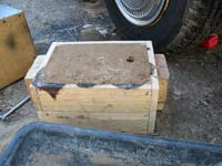
Then there are flasks. These are just two-part wooden boxes for the molding sand, built so they line up with repeatable accuracy. The molding sand itself is plain silica sand (not crushed stone) with a little Bentonite clay (cheap at clay supply places – ask potters where they go) mixed in. You might get lucky and have natural sand near you that already has a little clay in it. That about rounds out the essentials. Again, for techniques see the above books and sites. Be sure to check out the links on www.backyardmetalcasting.com and do some of your own web searches too.
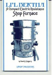
If you get really addicted to this, Gingery even has another small, cheap book on building a furnace that runs on electricity, using kiln heating elements. I’m not sure I’d try this stuff in the basement in any case, but some people have.
Starting simple
This is important. I started by simply making lots of ingots in a form I welded from angle iron. This was partly because I hadn’t gotten around to building the casting flask, and partly because I needed to reduce the physical size of my scrap aluminum heap. Otherwise it is actually easier to sand cast the ingots in open faced molds. But it is handy to have the ingot molds to pour leftover metal into.
Making ingots has a couple useful side benefits for scrap aluminum. It helps purify the metal by burning off any grease or paint in a melt separate from the final casting. It also allows some testing. I started cutting the ingots to see if there were gas bubbles in the casting, which are bad. This allowed me to refine the temperature control before I tried to do any molding. I was pouring far too hot at first, but aluminum is pretty forgiving.
Now let’s get to casting some simple parts. Let’s look at a project from the very beginning so you can see how I decided casting was even a good way to go. (It isn’t always.)
Draining Fuel
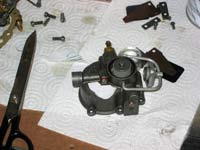
While working on last month’s article I remembered another motor issue that has been annoying me—the difficulty in draining the fuel from most carbs. This is essential at the end of the year, or fuel will go bad in the float bowl and foul the carb. This requires disassembly and cleaning, which is not difficult, but I don’t exactly relish doing it unless there’s a good reason.
I find that draining is actually even more important on motors left outside during the summer. The heat can evaporate the volatile components of gasoline in short order, leaving you with a clogged carb when you get around to starting a motor after a month of using other boats.
Most people deal with this by running the motor dry and spraying fogging oil in the intake. This is fine for the end of the season, but you can count on it fouling a set of plugs. Running the motor dry without fogging oil risks running the bearings dry, which is bad. Worse, you cannot count on this approach emptying the float bowl. It would be very convenient to be able to easily drain the excess fuel into a jar or back into the tank.
Unfortunately, it is usually difficult to get to the carb under the cowl, and many carbs have no drain plug. Even in the best case you need a tool to open the drain, it is hard to get a jar where you want it, and you always end up with a mess. It would be ideal if we could mount a drain line at the bottom of the float bowl and put a valve on it outside the cowl.
Of course, life is seldom so simple.
The first problem is that these fuel systems do not drain to a single low point. In fact they can’t. There is a low point at the inlet of the carb, and another at the bottom of the float bowl. These have to be drained separately! If we combine them into a single drain, we will have the same problem as the old carb we looked at last month, with fuel bypassing the float valve (through the drain “Y”). A check valve could fix this, but we still need to tap into the fuel system in two places.
That brings us to the second problem—how to securely attach drains to a carburetor casting. These castings are often only 1/8” thick or so, which makes it impossible to tap a hole to screw in a hose barb. Gluing to the surface does not seem especially reliable unless you can manage a really large gluing surface, which isn’t possible on any carb I’ve ever seen. I went for more security and shaped a piece to fit the float bowl, fastened from the inside with tiny countersunk screws, and glued it with JBWeld. This might be overkill, but I don’t want the bottom falling out of my carb when it counts.
So now we need patterns.
Patterns
This is simply a matter of making a wooden (or wax, or whatever) version of the piece we want to create in metal. I used wax in this case because it is very quick and easy to shape. I can even reuse it when I’m done, but sometimes it’s nice to keep those patterns around in case you need them again. You will if you break a part, get another motor with the same problem, make a friend whose motor has the same problem, etc.
The inlet drain
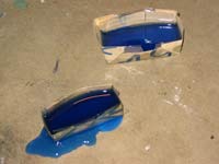
On carbs with no sediment bowl you can probably replace the inlet barb with a “T” fitting and two barbs. Then your inlet drain can lead downward directly from there. But if you have a sediment bowl, it will be the lowest point, and thus where you’d like to drain from. The best solution I could think of was to make an aluminum bowl with an extra knob of metal to mount a right angle hose barb. I could have worked this piece from a block of aluminum, but it seemed like less work to cast it to get closer to the final shape.
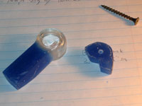
The pattern for this bowl drain could have been difficult, though. Fortunately there was no good reason not to simply use the glass part as the basis for the pattern. The final aluminum part will be slightly smaller due to shrinkage in cooling, but because the top is the gasketed surface, we have enough leeway to ignore it. So starting with a solvent-cleaned sediment bowl, I glue on a block of wax with some melted wax. My wax happened to be blue stuff leftover from making a candle, but plain sealing wax is fine.
Now we need to talk about “draft”. This means that vertical surfaces are given a slight angle so they can be pulled out of the sand. So looking at the side of a pattern, rectangles become slightly trapezoidal.
Since the draft on the glass bowl opens towards the mouth, so must the draft on my added piece. Note too how I filleted the corners. Real patternmakers make tools for this by welding ball bearings to the end of thin steel rods. Then they can heat them over an alcohol lamp to create appropriate fillets. I just used a hot butter knife. The smoother and harder it is, the better it releases from the sand.
Either way, the top lip of this casting will need to be lapped to seal well, and it is best to use the smallest practical hose barb. Mine have 1/8” pipe thread and 3/16” hose barbs.
Notice how I made part of this pattern far too big? Remember this. It is where the molten aluminum will enter the mold. I put it there because it will be easy to cut off the excess. This can be awkward if not planned in advance.
The float bowl drain
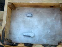
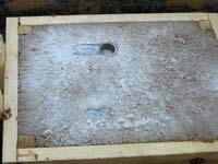
The second pattern was a bit harder to design, but no harder to make. I could have done the same shaping directly in aluminum, but it sure is quicker in wax! First I cut a paper shape that approximately fits a relatively flat spot on the bottom of the float bowl, taking care that there are no internal passages running through the float bowl’s wall at that point. (Usually there aren’t.) Note the extra bulge for the hose barb’s hole in the photo above.
Then I cast a block of wax to about the right thickness for the job – in this case about 1/2”. This is also how I made the piece to add to the float bowl. Don’t try to cast an exact size. Wax cuts like butter with a bandsaw, so always cast oversized. (Mine could have been thicker, actually.) And remember to add some wax as the blocks cool and shrink.
From there I only needed to trace my paper pattern, bandsaw the shape and finish it. A hand plane can make wax very smooth, and a carving knife works for smaller corners.
OK, time to make some molds. But I guess we’d better cover some terms.
Casting terms
- Cope: The top section of the flask
- Drag: The bottom section of the flask
- Flask: the two-part (sometimes more) vessel the mold is made in
- Follow board: a piece of plywood made to fit between the cope and drag
- Mold: The completed assembly of flask and sand with all necessary cavities to pour metal into
- Molding sand: sand with a bit of clay added to make it stick together
- Riser: A cavity rising above the pattern’s impression. As the metal below it cools and contracts, the metal in the riser “feeds” it, preventing gaps.
- Sprue: The opening the molten metal is poured through as it enters the mold
- Vent: a small hole poked through the top of the mold to release gasses and steam from the molding cavity.
There’s a lot more, of course, but this should get us through the article.
The mold
Ramming up a mold is simple in this case. First we dust the follow board with parting dust, lay out the patterns on it, and then dust the patterns. That’s the drag on top of the follow board.
Then we sift some fine molding sand over them and carefully press it in place by hand. Actually it doesn’t really sift – you have to sort of press it through a screen like grating cheese. Then we gently but firmly ram the rest of the sand in layers to fill the drag. This is a balancing act – loose sand makes a bad surface finish, and tight sand doesn’t let the steam and gasses out. (The more you try this, the more you want to hang OMC’s casting on your wall. They are indeed art.) Ramming the sand feels about like packing brown sugar, though to be honest I think I’m still packing it a little loose.
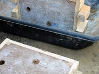
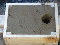
After screeding off the excess we add the bottom board and flip the drag over, then remove the follow board. Now is a good time to make an indentation where you will want your sprue. In this case I didn’t bother, because I knew I could put it at the middle of either end of the flask.
Then we dust it and ram the cope on top of it. I should have rammed a screw inside the sediment bowl to reinforce the sand. You’ll see why. Here’s the cope rammed and sprue cut. (I cut the sprue with a scrap of pipe, by the way.)
Now we remove the cope carefully and pull the pattern. The normal way to do this is to twist screws into holes in the pattern, tap them side to side slightly, and lift carefully straight up. If we have built enough draft into our pattern, it will come out cleanly. But the sand broke off in the sediment bowl.
I added a screw inside the sand to reinforce it, and as a result the pattern stuck to the cope. This was easier to deal with, however.
Gating
Now we need to get the metal to those mold cavities. Oops, more terms!
Runner: a longish channel leading away from the bottom of the sprue
Gate: A channel higher than the runner that takes the metal into the mold cavity
First the runner. It should be around 4 times the area of the sprue. The sprue is around 0.44 square inches, so the runner should be around 1.76 square inches. This is easy – cut it a bit under two inches wide and one inch deep. Why the increase in cross-section? We want the metal to slow down, which will even out the turbulence in our pour.
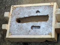
Note how the runner runs past the mold cavities into a dead end. This is so the very first bit of the metal does not go into the molds. This first metal will have the most contact with air and be the most oxidized. It is also the most likely to have loose sand in it.
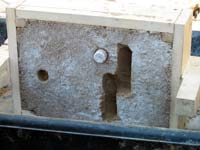
Now the gates. Since the gates need to be above the runner, it is common to put the gates in the cope and the runner in the drag. Here it is a simple matter to cut channels from the runner to where the pattern made imprints on the cope sand. The total cross section of the gates should equal that of the runner. I might have overshot a bit.
The overall idea of any gating plan is to convey the liquid metal smoothly to the mold cavities. Turbulence mixes air into the metal and oxidizes it. This is bad. It also tends to wear away the sand and carry it into the mold. This is also bad. Anything we can do to prevent air contact or turbulence is good.
We also need a pouring funnel on the sprue. A teaspoon helps turn the top 2/3 of the sprue into a funnel shape. ½” would probably be enough for these small castings, but modestly oversizing the feeding system usually doesn’t hurt.
The idea of the funnel is that we can pour quickly and smoothly into the funnel, and that this will keep the bottom choked with metal. This excludes air, which is good. You have to pour quicker than you would think to keep a ¾” hole choked with metal. Be sure to cut this funnel with the cope on its side. This makes it a lot easier to get the loose sand out of the way.
Last, we check the bottom of the sprue. We need a fairly deep well to help mitigate the turbulence of the pour – twice as deep as the runner and with a flat bottom so it doesn’t make the metal shoot back upwards. (Ever spray the kitchen sprayer into a ladle?).
Finally we smooth all the corners in the gating system with a spoon. All loose sand should be gently blown out. Use a piece of tubing or a drinking straw. After we carefully close the mold, we’re ready to pour.
Wow, this article is getting pretty long. Next month we’ll melt some metal.
Rob Rohde-Szudy
Madison, Wisconsin, USA
robrohdeszudy@yahoo.com |