| To
Part One
…and a new design!
Last month we measured an instant boat hull and
drew. Now we’re going to use common spreadsheet software
to help detect and correct our errors.
Spreadsheet graphing
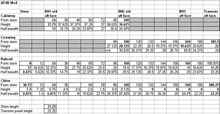
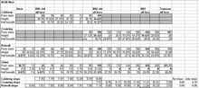
Let’s start by entering our measurements in the offsets
table. There is no one right way to set up an offsets table, so
do what suits you. However, I do recommend using bold print for
measurements taken from the actual hull, and plain text for those
taken from the drawing. We will assume the latter to be +/- 1/4”,
as mentioned above.
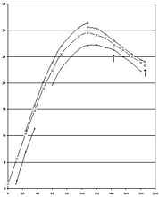
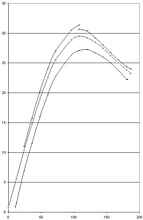
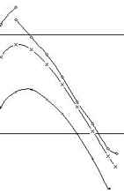
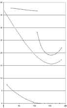
If we use spreadsheet software, we can use the graphing functions
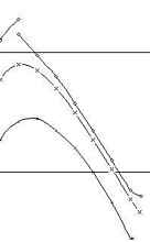
to double check our work. I use a scatter plot, as this plots
x,y coordinates so we can see if the line is actually fair.
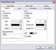
Note that in MSExcel you can format each data series to make
a “smoothed line” between the points.
The scales are not equivalent to the actual boat, but because
the curve looks fair, everything is probably in order. Actually,
it is easier to see something out of order when you intentionally
distort the scale.
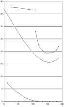
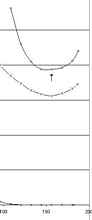
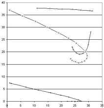
This reveals a couple things. First, at the far right I have
two points on the transom that are the same distance from the
stem (see arrow). They shouldn’t be. This was a data entry
error. The coaming distance from stem should actually be 187 inches.
It still jumps out of line, we’ll fix that in a minute.
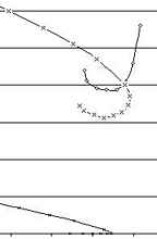
The other arrow notes some points that are kinked out of line.
Here we need to decide which points are more likely to be correct.
If any of these were measurements directly from the hull, I would
favor those. However these are all from the drafting, so we are
several layers of potential error from the real thing. However
in this case I notice that my rubrail point is kinked in on the
same station where my chine is kinked out. I think I probably
made a bad measurement on that station. Tweaking those half breadths
unkinked things. I also added the missing point on the chine and
made a few other more minor adjustments, since this foreshortened
view reveals more errors than the actual drafting.
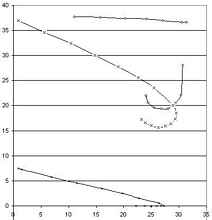
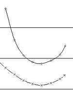
Let’s look at the updated profile with the other two views
and make sure we didn’t screw anything up there. It is best
to check this after every change.
Except for a very slight kink in the cabintop, the stern is our
only remaining problem. The three lines on the transom should
be colinear in all three views, which is currently not the case
in any view. So what are we surest of? The length to the transom
top and bottom were measured from the actual boat, as was the
transom height and transom bottom width.
I think we can be pretty sure I have the distance from stem a
little long for the rubrail. Changing that and moving it slightly
outboard seems to get things in line. But since we’re doing
math, why not check all of the lines that should be straight?
Checking for colinearity with slopes
The side of each bulkhead, the stem and the transom should be
straight, which means all points that fall on them should fall
on the same line. We can check for this mathematically.
This is actually pretty easy since we’re dealing with known
points. All we need is slope, which is rise over run. (Divide
the change in height between two points by the change in half
breadth between two points.)
I do this by figuring the slope of the line formed by the point
on the chine and the point on the cabintop. Then figure the slope
of the line formed by the point on the chine and the point on
the rubrail for the same station. Since they start with the same
point, all the points are on the same line if the slopes are the
same.
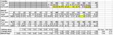
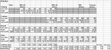
The transom is a little trickier, since we need to whip out the
Pythagorean theorem to come up with an accurate “run”
figure. I also added a “flat slope” for the transom
to make sure the rubrail and coaming lines (from chine) have the
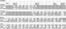
same slope as viewed from above. Here is the table of offsets
with slopes added at the bottom.
Yikes, these are all over! Actually they are not as bad as they
look, but the transom is still noticeably off. The flat slope
is looking good (and it does on the plan view), but we’re
still not in line. Let’s look for patterns.
Notice that the differences between the rubrail and coaming are
all in the same direction except the one at BH2. I have a lot
more confidence in the curve I drew for the rubrail, because it
is a nice, easy curve. For that coaming I had to fight the spline
to keep it on the page without nailing it down. At BH2 and changed
the coaming half breadth only 1/8” and the slopes match
close enough to leave it. This is well within the expected error
for drafting. One station aft of BH2 I had to move the point 1/2”
inward. This is a bigger change, but still quite believable, given
my struggle with the spline. Moving aft I changed stations by
1/4”, 1/8”, and 1/8”.
This brings us to BH3. Here I believe the actual measurement
from the boat on the coaming more than I believe my drafting measurement
on the rubrail. It only took a 1/8” change to fix it, but
this necessitated a 1/8” adjustment to the station forward
of that to re-fair the line. This didn’t affect my modification
of the coaming, but it could have.
Back to adjusting the coaming, a 1/8” adjustment of the
station aft of BH3 does the trick.
This brings us to the transom, which is seriously messed up.
What I call “flat slope” is the transom edge angle
as viewed from above. This is in pretty good shape. But the slope
along that line is not good at all. The problem is in the “side
slope” component. The measurement I’m least confident
in here is the distance from stem at the rubrail. I had to move
this a full inch to get it right. I suspect this means I counted
wrong when writing down the measurement from the drawing.
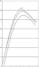
Here’s where we stand:
Boy, that sure got kinked up in the plan view. We also have
a noticeable unfairness in the profile. Let’s fix that first
and see if it fixes the plan view. It did, and it only took 1/8”
of adjustment in both height and half breadth.
Obviously we still have issues at the stern. Our slopes at the
transom look great, but I know I didn’t kink any wood that
tight. That kink would require steam or many more laminated layers
than the three I used. Again we look for what we doubt the most.
At the station between BH3 and the transom nothing was measured
from the actual boat, so let’s see what we can do. The biggest
kink is in half breadth of the coaming. It is fixed by adjusting
the coaming 1/8” in half breadth and 1/4” in height.
Now we have a much improved offsets table, and any bulkheads
made from it should be considerably more accurate.
Onward Toward a New Design
Now we get to the reason I started this whole measurement process.
After spending a season with my made-over AF4B, I finally knew
what I needed to do to have my idea of the ideal small family
powerboat. I needed only a small cabin for the potty and for hanging
up life jackets and other things that should stay dry. Maybe for
kids to nap in occasionally. I especially needed a bigger bow
well for both kids to ride up there together. Even doing both
of these things I could still squeeze out a bigger cockpit, which
is where all the grown-ups always want to be.
I’ll have more detail later on how this worked out, but
for now we need some dimensions for new bulkheads. How do we do
it?
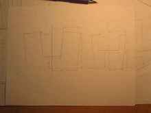
New Bulkheads
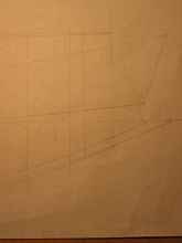
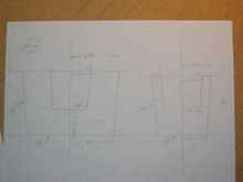
First we need to know the fore and aft position of these bulkheads.
Then we make lines perpendicular to the baseline at these positions
on the profile/plan view. In this case I wanted them 3.5 and 7
feet aft of zero (top forward corner of planking). We already
have a section line at 7, so we draw in 3.5.
This provides us the height on the profile view and the half
breadths on the plan view. We transfer these to the section view.
Knowing this we can draw the shape of our new pieces of plywood.
But we’re not done. We still need to know the…
Bevels
Michalak discusses how to figure bevels in his articles on hull
design. But Jim is a real engineer and his method for calculating
bevels reflects that. For him, advanced math like cross products
and matrix multiplication are a pleasant stroll down memory lane.
For most of us they are excruciating mental exercise to remember
or learn. In my case it was learning—I can assure you that
they don’t teach that stuff to music majors.
Of course it was after I bothered to learn all that math that
I discovered a far simpler way. You can do it right on the plans
if you have a section view. (If you have a table of offsets, you
can draw one.) Best of all, it works exactly the same as Jim’s
method. It’s just graphic rather than mathematical.
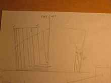
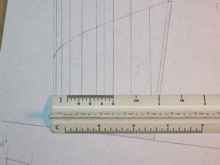
First we need a line at right angles to our bevel line, which
also connects to the next station line. Let’s call its length
on the section view a. This line should be the same length no
matter where you put it on that bulkhead, since the lines defining
the sides should be parallel at each station. (If they’re
not you can’t rip constant-angle bevels!) I didn’t
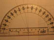
even draw the line. I just lined up the scale rule and squared
it up with the drafting triangle – I’m measuring about
2.25” starting at zero on the scale rule. (I removed the
triangle to make the photo clearer.)
Easy, right? Well, if our bulkhead is square athwartships and
plumb, that tells us all we need to know. The other part we need
is the distance from our bulkhead to the station that contains
the point that a connects to. The plan or profile view will have
this. Let’s call it b. In this case it’s the 6”
between our new bulkhead at 3.5 and the station line at 3.
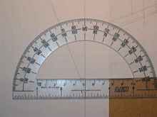
Now we draw a triangle. A draftsman would project it right on
the plans, but I do it on separate paper to keep the plans cleaner.
First make a line and mark off the length b. At right angles to
one of the ends of b, mark the length a.
Then connect the unused ends of a and b. The acute angle is your
bevel angle! I extend the lines to make it easier to measure with
a protractor.
There’s no reason to draw separate angles as long as the
station spacing stays the same. Just mark off new lengths for
a and fill in the angle line.
These results let us put bevel angles on the bulkhead drawings.
You can actually do the same thing for rolling bevels too. You
just need to use this method figure the bevel angle at both the
sheer and chine. Then after making some initial cuts on the bulkhead’s
framing stick, you strike a line between the two cuts and do some
careful planing to finish it. Fortunately, we don’t need
to go to the trouble with untwisted instant boats.
If you don’t want to mess with the protractor, you can
calculate the angle from the lengths of a and b. Pythagoreas can
help you out with something you might remember from high school
trigonometry. The figures we know are side opposite and side adjacent
of a right triangle. Tangent is the ratio of the former divided
by the latter. To turn tangent into an angle, we calculate its
arctangent. In spreadsheet software like MSExcel this looks like
“=degrees(atan(a/b))”. If you refer to other cells
for the variables, this can be very quick indeed.
So now you tall guys know how to refigure the bevels when you
need to move a bulkhead to be able to sleep in your cabin without
contortions. Or how to reduce a cabin to a cuddy.
Checking Measurements
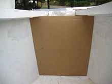
Let’s fit some real bulkheads! I made cardboard patterns,
since it doesn’t pay to trust anyone’s draftsmanship
at 1/12 scale for an exact fit. My fine pencil line is at best
the equivalent of 1/8” wide, after all. Surprisingly, the
front bulkhead at 3.5 fits perfectly!
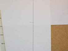
But bulkhead 7 leaves a gap at the top of each side.
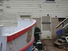
This means we had better double-check some measurements. As it
turns out my measurement at the top of the aft cabin bulkhead
was wrong. This is a lot easier to see after the cabin top is
cut off. I guess I should have measured with sticks instead of
a tape measure, but I this is at least partly the result of a
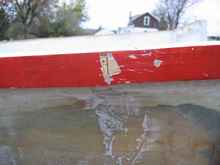
small inaccuracy in the original hull. See how these cabin top
stringers bulge out unfairly?
Here’s why. There’s an unsupported butt joint.
With this in mind I did not redraw the plans using this “corrected”
measurement, since I think the splined lines are closer to what
the hull is supposed to be.
I should also point out that it is best to consult the designer
before attempting to move bulkheads around. But I guess I’m
a designer now that this boat has evolved this far.
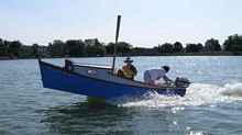
A new design – Sandy Shoal 16
Complete plans are available through the Duckworks
store, and I’ll be telling you more about this
design next month.
Rob Rohde-Szudy
Mazomanie, Wisconsin, USA
robrohdeszudy@yahoo.com
*****

|